
A brief guide: How the Flying Fuel Cell™ works

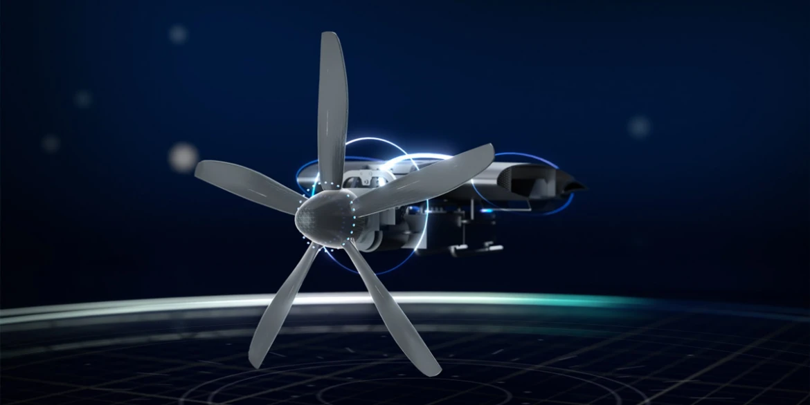
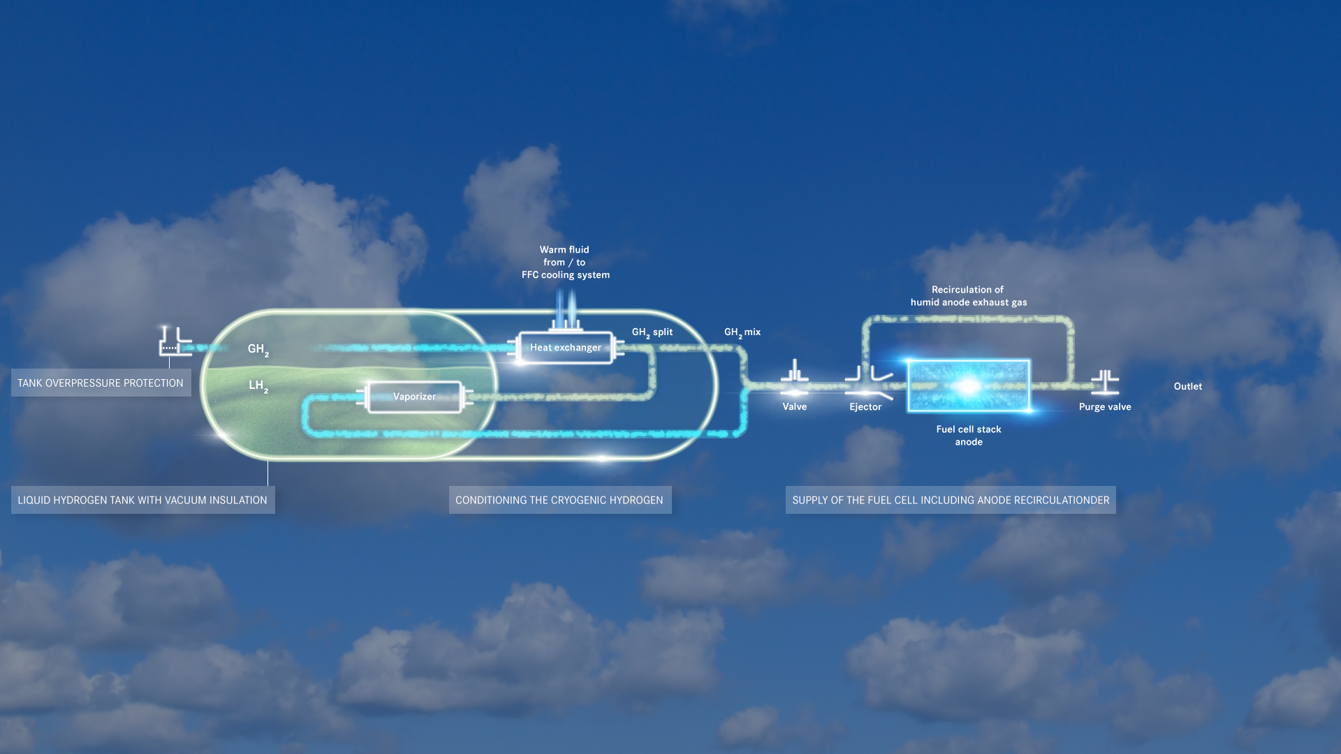
MTU’s FFC emits no CO2, no NOx, and no particulates; all it produces is water. That means this propulsion concept is virtually emissions-free.

author: Isabel Rauschert | 3 mins reading time | updated on: 09.06.2026 |

author:
Isabel Rauschert studied political science and communications. At MTU, she coordinates the editorial process of AEROREPORT and is responsible for the conception and development of its content.

Kopf

What is the Flying Fuel Cell™?

The Flying Fuel Cell™ (FFC) is MTU Aero Engines’ fuel-cell propulsion concept. As in every fuel cell, a reaction between hydrogen and oxygen from the air produces water and releases electrical energy. A highly efficient electric motor then uses this energy to drive a propellor via a gearbox.

MTU is working on a revolutionary propulsion concept, the FFC, which aims to achieve virtually emissions-free flight through complete electrification of the powertrain.

What are the advantages of the FFC?

This propulsion system does not produce any emissions of CO2 or NOx or particulates—its only emission is water. In other words, the FFC reduces the climate impact of aviation by as much as 95 percent—i.e., to virtually zero. Since the propeller is the only remaining source of noise, the FFC also emits much less noise. A further advantage is that the platinum used in the fuel cell is highly recyclable. When processed properly, it can be reused almost indefinitely.

What components go into the FFC?

The core components of a high-performance flying fuel-cell system are the stacks and an intelligent integration of all lines.

- file://QczY7WEha3sHI5oQ
  • Fuel cell stacks: Conversion of hydrogen and oxygen into water and electrical energy.
  • LH2-Tank: Storage and supply of liquid hydrogen for the electrochemical process in the fuel cell. Liquid hydrogen is converted into gaseous hydrogen and then sent to the hydrogen line.
  • Hydrogen line: Conditions the gaseous hydrogen coming from the LH2 tank system to give it the appropriate temperature, desired pressure and ideal humidity before conversion in the fuel cell stacks.
  • Heat exchangers: Serve to dissipate heat so as not to exceed the permissible temperature in the fuel cell and all subsystems.
  • Air line: Streams of air are directed precisely to where they can provide the necessary oxygen for the electrochemical reaction. The air line, too, must supply air to the stacks at the appropriate pressure, temperature, and humidity. After MTU had already successfully tested the air line in an earlier configuration, experts conducted tests in Munich in early 2026 on a further developed version of the subsystem with enhanced functionality and performance.
  • Power line: Takes the electrical energy from the fuel cell stacks and converts it into mechanical energy using a motor control unit (MCU) and an electric motor. The power line is also a separate network that supplies all of the system’s electrical consumers.
  • Cooling line: All equipment is cooled or heated depending on the flight phase and the flight conditions in order to optimize system thermodynamics and aircraft energy management. The heat is regulated in the system by way of a cooling liquid and the smart interconnection of devices. The excess heat is then released to the outside air through a heat exchanger.
  • Electric motor: Converts electrical energy from the fuel cell into mechanical energy and is part of the power line.
  • Propeller: Converts mechanical energy from the electric motor into thrust.
  • Control line: The control line is almost invisible, but it is a key to success with the FFC, because it ensures the intelligent interaction of all components in all phases of flight. The control line is the system’s brain. It combines all sensors, data and actuators to form a perfectly harmonious orchestra.

The Flying Fuel Cell stacks consist of individual cells: a membrane electrode assembly (MEA) and a bipolar plate (BPP).

The heart of the FFC: the stacks

A fuel cell stack is the core component of a fuel cell system. Because a single cell generates only a relatively low voltage, up to several hundred cells are connected in series and stacked to achieve the required power output and voltage. MTU has nearly completed the critical design review for its first electric 600 kilowatt propulsion system. This marks the transition to the manufacturing and assembly phase. At MTU in Munich, the first state-of-the-art fuel cell stacks are already being produced.

How does the fuel cell work?

Each fuel cell consists of two plate-shaped electrodes (anode and cathode). At the anode, hydrogen molecules (H2) release electrons to become positively charged hydrogen ions (H+). The free electrons flow as usable electricity via a conductor to the cathode, where they join with oxygen atoms to form negative oxygen ions (O2-).

Meanwhile, the hydrogen ions pass through the membrane from the anode to the cathode before combining with the oxygen ions at the cathode to form water while releasing heat. Compared to other systems, fuel cells achieve high levels of efficiency.

Fuel cells convert hydrogen and oxygen into electricity, heat, and water – with impressively high efficiency levels.

How is hydrogen provided and stored in the FFC?

Together with its partner MT Aerospace, MTU is developing a complete liquid hydrogen fuel system comprising tanks, sensors, heat exchangers, valves, safety systems, and controls. After MTU and MT Aerospace had proven the effectiveness of the liquid hydrogen storage and supply system in various operating scenarios, MTU carried out tests with liquid hydrogen, the FFC operating medium, in Munich. MT Aerospace had previously used liquid nitrogen for the tests, which is easier to handle due to its physical properties. The MTU test campaign with LH2 was successful and provided validation of the concept, including all sensors and functions required in the aircraft. Tests of a product-ready, full-system FFC demonstrator are planned for 2026—and the liquid hydrogen system will be a central component of this.

- file://EeCU3XnwfZhJfVUY
  • Liquid hydrogen tank with vacuum insulation: Liquid and gaseous hydrogen (LH2 & GH2) are stored at T ≈ –250°C in a double-walled vacuum-insulated tank.
  • Conditioning the cryogenic hydrogen: Waste heat from the stack heats the H2 in a heat exchanger. GH2 evaporates through recirculation of a warm partial GH2 flow by the vaporizer in the tank.
  • Tank overpressure protection: A spring-loaded valve protects against excess pressure.
  • Supply of the fuel cell including anode recirculation: A valve controls hydrogen flow according to the operating point. The anode intake gas is humidified through passive recirculation of humid anode exhaust gas with the help of an ejector (suction jet pump).

Highly efficient and compact: The electric motor for the FFC weighs just 40 kilograms, delivers 600 kilowatts of power, and integrates seamlessly into the fuel-cell system.

What are the advantages of the electric motor?

Together with its subsidiary, the electric motor manufacturer eMoSys, MTU is developing a highly efficient electric motor for the FFC. It will drive the propeller of future aircraft and has several advantages. For example, the new motor weighs just 40 kilograms, has a diameter of only 300 millimeters, and delivers a continuous output of 600 kilowatts. It is efficiently integrated into the architecture of the fuel-cell system, and its design supports the use of several fuel-cell stacks with no need for complex inverters. The initial results are promising: As part of a demanding test campaign, the 600 kilowatt powertrain reliably reached its maximum continuous output for the first time. A high efficiency of more than 96 percent was also confirmed—both during takeoff and in cruise mode.

Where can the FFC be used?

The Flying Fuel Cell will initially be used in regional air traffic on shorter routes. The next generation of FFCs will then fly on short- and medium-haul routes.

What are the next development steps?

The clean aviation research project HEROPS (Hydrogen-Electric Zero Emission Propulsion System) has been running since mid-January 2024. It aims to build on MTU’s FFC to develop technologies for climate-neutral, hydrogen-powered electric powertrains that will get regional aircraft into the air starting in 2035. Under the leadership of MTU, seven partners initially want to spend no more than three years analyzing propulsion systems with an output of up to 1.8 megawatts and then build a HEROPS ground demonstrator. The aim is to establish the feasibility of the new, groundbreaking technologies and their scalability to outputs of between 2 and 4 megawatts on the basis of a modular propulsion architecture. With the completion of the initial design phase, the first major milestone was achieved in 2025. MTU’s industry partners in HEROPS are MT Aerospace, RTX’s Collins Aerospace, Lufthansa Technik, and Eaton. The research partners are the Royal Netherlands Aerospace Center (NLR) and the Vienna University of Technology.

The Flying Fuel Cell reduces climate impact by up to 95 percent. Since it emits no CO2, no NOX, and no particulates, the FFC is virtually emissions-free. What’s more, the entire propulsion system is much quieter.

What role do tests play in the next phase?

Two key test cells for the FFC are currently being set up at MTU’s Munich site. A stack test cell for outputs of more than 500 kilowatts per stack has already been in operation since 2025. At the same time, a second facility for the overall system is under construction. In the future, all subsystems will be tested together there to verify the functionality of the complete propulsion system.

What challenges are associated with certification?

With the Flying Fuel Cell™, MTU is entering new technological and regulatory territory. As existing certification frameworks need to be partially adapted for this novel propulsion system, the company has been working closely with the European Union Aviation Safety Agency (EASA) since 2021. At the end of February 2026, this collaboration was extended through a second so-called Innovative Partnership Contract. The goal is to establish the regulatory foundations for an entirely new propulsion system at an early stage.


You may also be interested in these articles:


AEROREPORT reports on high technology and excellent service “made by MTU” as well as on general aviation topics.

AEROREPORT is the online magazine of MTU Aero Engines. Flying and the technology that makes it possible are fascinating and bring up a broad range of issues: more than a hundred years of history and many questions about the future of aviation in the face of climate change, population growth, and resource scarcity.